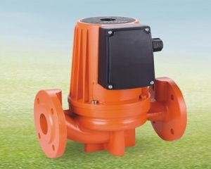
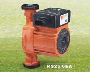
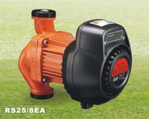
To sizing a water pump for heating system, to the process flow and heating system requirements, should consider from 5 aspects, as liquid delivery volume, pump head, liquid properties, piping layout, and operating conditions.


1) Flow rate is one of the important performance data for water pump size, which is directly related to the production capacity and conveying capacity of the entire device. For example, in the design process, the normal, minimum and maximum flow rates of the pump can be calculated. When selecting the pump, take the maximum flow rate as basis, taking into account the normal flow rate. When there is no maximum flow rate, usually 1.1 to 1.2 times the normal flow rate can be taken as the maximum flow rate.
2) The pump head required by the installation project is another important data for pump selection. Generally, the head with a 10% to 12% margin is used to select the type.
3) Liquid properties, including the name of the liquid medium, physical properties, chemical properties and other properties. The physical properties include temperature c, density d, viscosity u, etc., which are related to the calculation of pump head, effective cavitation flow rate.
For example, the air source heat pump system adds antifreeze to prevent freezing and cracking of the water pipes in winter. the specific gravity and viscosity of the water must be considered when using antifreeze in the air source heat pump system, otherwise it will cause unnecessary losses.
1. Working principle of circulating water pump
The main flow parts of the circulating water pump are the suction chamber, the impeller and the pressurized water chamber. The suction chamber is located in front of the impeller and plays the role of guiding the liquid to the impeller; the pressurized water chamber mainly has three forms: volute type, guide vane and space guide vane; the impeller is the most important working element of the pump, the impeller consists of a cover plate and a middle blade.
2. Flow rate of circulating water pump
If not consider the simultaneous utilization rate, the unit is selected according to the value provided by the product sample × a factor of 1.1 to 1.2 times.
If the simultaneous utilization rate is considered, the following formula is recommended for calculation (Q is the total load without considering the simultaneous utilization rate):
G=Q×0.86/ΔT
Where:
G—Circulating water flow m3/h;
Q—Total load kW;
ΔT —The temperature difference between inlet and return water ℃ (20℃~25℃ for radiator system, 10℃ for floor heating system, and 5℃ for air source heat pump system);
The flow rate of the water pump = (1.1~1.2) × the circulating water volume of the system.
3. The head of the circulating water pump
Because of the total water pressure drop of the most unfavorable loop in the supply/return water pipe network, the empirical formula for calculating the most unfavorable loop resistance is as follows:
H max =ΔP 1 +ΔP 2 +0.05L(1+K)
Where:
ΔP 1 —The water pressure drop inside the heat source device;
ΔP 2-the water pressure drop of the most unfavorable loop, the water pressure loss of each terminal device in parallel is the largest one (or part) of the connecting pipeline;
0.05L—The loss along the way is about 5mH 2 O per 100m pipe length (estimated);
K—The ratio of the sum of the equivalent lengths of local resistance in the most unfavorable loop to the total length of the straight pipe; when the most unfavorable loop is longer, K is 0.2~0.3; when the most unfavorable loop is short, K is 0.4~0.6.
Pump head (mH 2 O)=(1.1~1.2)×H maxing
